
Practical development representation of the railing with corner gaps for optimal fabrication.
See how fast it worksThe development view should ideally show the railing “in one piece.” But that is either not possible or doesn’t make sense: often the parts are laterally offset. That’s why the program displays the development (in the post plane) with gaps at the corners.
This way, elements that are not in the post plane can be shown shortened or extended.
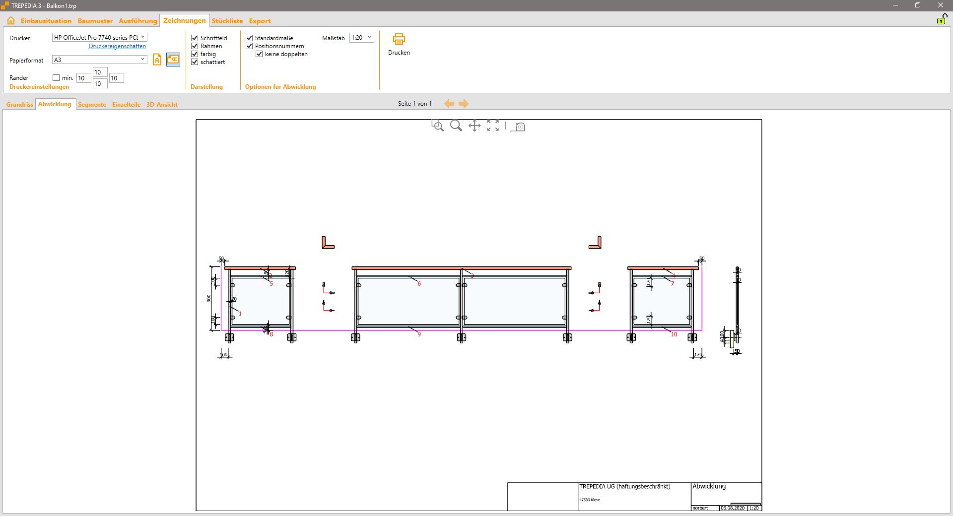
Development drawing with corner gaps for better clarity
Problem: A continuous development view would result in overlapping or distorted areas.
Solution: Gaps at the corners allow a realistic representation of all elements.
Advantage: Elements outside the post plane are shown with correct proportions.
The development drawing is especially valuable for workshop fabrication, as it shows all elements in their actual size and position – even if they are not all in the same plane.